A Brief Guide To Linkage Design
This guide will help you design a cost effective and suitable linkage for you application. However, please contact our Technical Department for detailed advice.
THE LINKAGE END FITTINGS
Your particular application will determine the selection of end fittings – clevises, ball joints, rod ends etc. Will your linkage be affected by a) environment – dust heat/cold, b) high/ low loads, c) small / large angles of “articulation”, d) weight, e) restricted space, f) life expectancy, g) initial assembly method and subsequent need for easy removal.
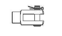 |
Obviously your choice will be affected by the shape of the part that the linkage will be joined to. If one end is connected to an activating valve, for instance on the controls of a Backhoe Loader, then invariably a Clevis (Yoke or Fork End) with relevant Clevis Pin will be required. DIN 71752 CLEVIS FITTED WITH NBM CLEVIS PIN AND SLM CLIP. |
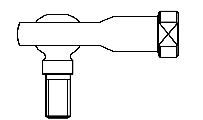 |
Clevises are normally used where articulation is only required in one plane. In most cases the other end of this type of linkage would require some form of right angle Ball Joint or studded Rod End as they are usually bolted directly into a Bell Crank or Lever of some sort. Ball Joints provide conical movement of the male Ball Stud. When specifying this type of right angle Ball Joint consideration should be taken as to the location of the joint. Is it up inside the Cab or exposed to the elements under the machine. Construction equipment can encounter some very harsh conditions. Where will the equipment be used, in the salty atmosphere of a dockyard, in the Alaskan tundra or out in the Arizona desert? HMSS SERIES ROD END WITH RIGHT ANGLED THREADED BALL STUD. |
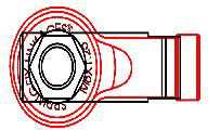 |
When designing a control linkage a Ball Joint with very little or no backlash is an advantage to provide a nice positive feel to the controls of the machine. Vibration is another factor. A Ball Joint fitted to the control pump of a Skidsteer will encounter a tremendous amount of vibration and could promote premature wear. When space is an issue, a Ball Joint is usually preferred over a Rod End (Sometimes known as a Rose Joint). The SAE D, F and P Types normally are sufficient. However these type of Ball Joint are low cost and by design do not provide a backlash free link. WHERE A PART IS TO BE USED IN A CONFINED SPACE, A BALL JOINT IS PREFERABLE OVER A ROD END SHOWN HERE WITH THE RED OUTLINE AGAINST THE BLACK OUTLINE OF A TYPICAL BALL JOINT. |
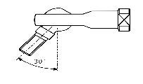 |
If the application requires a large angle of articulation, our HMFSS Rod Ends are manufactured with a waisted neck to provide around 60° inclusive of conical movement. HMSS SERIES ROD END PROVIDES 60° INCLUSIVE CONICAL MOVEMENT. |
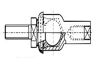 |
In some instances where there is minor misalignment between parts to be linked, an In-line Ball Joint will be suitable. Noting: these are not designed to be used under tension or where there is severe vibration. IN-LINE BALL JOINT WHERE LINEAR MISALIGNMENT IS AN ISSUE. |
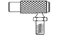 |
The method of assembly on your production line needs to be considered and whether the linkage may subsequently need to be disconnected and reassembled at times. If you need easy removal we suggest our Q Type and P type. Q TYPE BALL JOINT PROVIDES QUICK RELEASE CAPABILITY. |
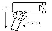 |
Ball Joints are usually loaded radially. However, axial pull out loads should still be considered to avoid the ball stud pulling out of its corresponding socket when fully articulated. Life expectancy is dependant on many application variables. Therefore we ask our customers to carry out their own testing once we have recommended a suitable linkage configuration. BALL STUD SHOWN IN OVERARTICULATED POSITION SO THAT NECK OF STUD IS FORCED AGAINST THE EDGE OF THE BALL CAVITY. THIS CONDITION SHOULD BE AVOIDED. |
Table 1. gives a brief summary of the advantages and disadvantages of each type of Ball Joint. This table should be read in conjunction with our catalogue or the catalogue pages of this website.
CONNECTING ROD
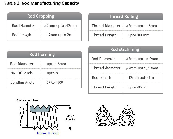
We recommend the use of a) cropped to length and thread rolled rods which provide a considerable cost saving compared with the alternative b) machined rods with cut threads. Cropped Rods do not provide a chamfered end but it is still easy to “start a thread”. We recommend that the rod is specified with left and right hand threaded ends to provide more precise length adjustment. Obviously this is suitable only for straight rods without bends. Spanner flats or knurls can also be added to aid adjustment. Where the linkage is to be fitted into a confined space, Rods are available with simple or compound bends and detail of this can be found on table 3.
For cropped and rolled rod sizes and for standard spanner flat sizes see page 51 of our catalogue. Of course we can also manufacture machined rods and recommend materials such as 070M20 where the rod is to have another component welded to it.
TABLE 1.
ADVANTAGES OF DIFFERENT TYPES OF BALL JOINT (REFER TO OUR CATALOGUE FOR DETAILS).
| ADVANTAGES | AM | BM | CM | DM/DI | FM/FI | HM/HI | IM | PM/PI | QM/QI | RM |
| Smooth action, backlash free | ? | ? | . | . | . | ? | . | . | . | . |
| Suitable for vibration applications | ? | ? | . | . | . | ? | . | . | ? | . |
| May be assembled by customer or to pre installed stud | ? | ? | . | . | . | . | . | ? | . | . |
| Available with dust seal | ? | ? | ? | ? | ? | . | . | . | . | . |
| Suitable where light weight is an issue | . | ? | . | . | . | . | . | ? | . | . |
| Non corrosive Body | . | ? | . | . | . | . | . | . | . | . |
| Low cost | . | ? | . | ? | . | . | . | ? | . | . |
| May be moulded directly onto Link Rod | . | ? | . | . | . | . | . | . | . | . |
| Includes Safety Clip | . | . | ? | . | . | . | . | . | . | . |
| High pull out loads | . | . | ? | ? | ? | ? | ? | . | . | . |
| Available in Stainless Steel | . | . | ? | . | . | . | ? | . | . | ? |
| Suitable where limited space is an issue | . | . | . | ? | ? | . | . | ? | . | . |
| Inch version available | . | . | . | ? | ? | ? | . | ? | ? | . |
| Good wear resistance | . | . | . | . | . | ? | . | . | . | . |
| Durable construction | . | . | . | . | . | ? | . | . | . | . |
| Male threaded Body available | . | . | . | . | . | ? | . | . | . | ? |
| Quick release | . | . | . | . | . | . | . | . | ? | . |
Note:
Working temperature of Ball Joint / Rod End is dictated by the following:
Nylon maximum working temperature = 100°- 120°C (212 – 248°F)
Grease working temperature = -40° to 120°C (-40° to 248°F)
GENERAL SPECIFICATION TIPS
We can also offer a cost saving by securing a Clevis to the end of a Rod using silver solder or loctite. This method will render a saving of approximately 25% over a welded joint. When silver soldered, the parts are plated after assembly.
We always recommend the use of standard catalogue items rather than specials which can incur high costs unless required in large quantities.
Specifying a “loose assembled linkage” can save the extra cost of a setting fixture especially on short batch runs. A linkage quoted as such would be supplied with locking nuts finger tight.
Specify LH/RH threads on rods to provide infinite adjustment. RH/RH would require a tolerance equal to the thread pitch between the centres of the end fittings.
Specifying Ball Joints with a Gaiter fitted provides better protection from ingress of foreign bodies. Establish any requirements for tight tolerances at the onset of a project. Our general tolerances are ?0.8mm (?0.030″) ?2? for formed rods and linkage assemblies and ?0.25mm (?0.010″) for machined parts. However we can hold tighter tolerances on critical dimensions as long as they within the capability of the process.
Note that if available, we can import emailed .iges or parasolid files into our 3D CAD system. When possible, it is best to get Springfix involved at the early stages of a development program so that we can advise you on the best cost effective solution to your linkage requirements.
We usually supply complete linkages with the end fittings pre-assembled to connecting rods ready for you to fit on your production line. However we are happy to provide you with the individual parts for you to assemble your own linkages
MATERIALS
Most of our Ball Joints are manufactured from 230M07Pb (SAE12L14). If you are designing complimentary turned parts such as a Turnbuckle, it is preferred that you specify this same material. This material is readily available in small quantities and has good machineability. If the inclusion of lead is a problem, our current non leaded alternative is 230M07 (SAE 1214) which requires a cycle time about 20% slower and hence incurs more cost. However, 230M07Pb has a lead content that is within the “Vehicle End of Life” directive. Some designers specify 220M07. This specification is not generally available and is superseded by 230M07.
 |
 |
FINISHES
Our standard finish is Zinc plate and yellow passivate to BS3382 or BS EN 12329:2000 for non threaded parts. Most Platers will have a plating line constantly running this specification. However, if you require improved corrosion resistance, we have suppliers who can provide our parts plating to JS500 or Zinc Nickel Alloy which can provide up to 2000 salt spray resistance. We suggest Zinc plate and clear passivate when producing an assembly using our C or I type Ball Joints. This is purely for cosmetic reasons as our C and I types are finished Zinc and clear passivate.
When specifying a finish, it is worth noting that the darker the passivation, the greater the protection. Some customers take our Ball Joints in Olive Drab for that reason.
As a general guide the following applies when salt spray tested to ASTM B-117 although these figures can vary quite considerably as lot depends on the process and the shape of the part.
Clear passivation will give approximately 12 hours to white rust and a further 24 hours to red rust.
Yellow passivation will give approximately 48 hours to white rust and a further 48 hours to red rust.
Bronze passivation will give approximately 72 hours to white rust and a further 72 hours to red rust.
Olive Drab passivation will give approximately 96 hours to white rust and a further 96 hours to red rust.
JS500 provides approximately 400 hours protection for barrel plated parts to ferrous corrosion. Zinc Nickel Alloy will give approximately 2000 hours to ferrous corrosion.
It is worth noting that Zinc plate and clear passivation, JS500 and Zinc Nickel Alloy with a clear passivation all comply with the “Vehicle End of Life” directive in that the finish does not include Hexavalent Chrome (Cr6). Other finishes that we have supplied include Dacromet, Phosphate and Oil, Chemical Black and Nitrotec.


